In a live network, the eNodeB generally uses a transport network to connect to adjacent NEs, such as the S-GW, MME, IP clock server, and U2000. Layer 2 and Layer 3 networks are commonly used in LTE networking.
Layer 2 Networking
Layer 2 networks, also called
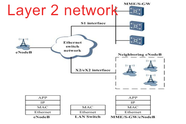
Ethernet switch networks, are commonly used in LTE. The eNodeB accesses this network through the FE/GE/10GE port. It shows a Layer 2 network in Figure.
 |
| Layer 2 Network |
The Layer 2 network provides the bearer function at the MAC layer. The eNodeB does not provide the Layer 2 Ethernet switching function, and supports only packet forwarding based on IP addresses. After packets are encapsulated into frames, the Layer 2 switch forwards packets
based on the source and target MAC addresses.
The MAC layer is a sublayer of the data link layer in Ethernet. Complying with IEEE 802.3, the
MAC layer provides functions such as addressing, data storage, and data retrieval.
Users must configure the Ethernet port, MAC layer, and IP layer, as described in table
 |
| Layer 2 network configuration |
At the MAC layer, an eNodeB can use the following VLAN tagging methods:
- VLAN group: VLANs and VLAN priorities are configured based on next-hop IP addresses, subnet masks, and packet types.
- Single VLAN: VLANs are configured based on next-hop IP addresses and subnet masks, and VLAN priorities are configured based on the mapping between DSCP values and VLAN priorities.
Layer 3 Networking
Layer 3 networks, also called IP networks, are commonly used in LTE. The major devices are routers. The eNodeB accesses the IP network through the FE/GE/10GE or E1/T1 port. It shows a Layer 3 network in Figure.
 |
| Layer 3 network |
The Layer 3 network provides the bearer function at the IP layer. Users must configure the physical layer, data link layer, and IP layer.
List the configurations based on the E1/T1 port
 |
| Configurations of a Layer 3 network over E1/T1 |
List the configurations based on FE/GE/10GE port
 |
| Configurations of a Layer 3 network over FE/GE/10GE |


Post a Comment