A link budget is the term used that accounts for the power received at the receiver. This accounts for all of the gain and losses from the transmitter to the point at which it is received by the receiver. It includes losses from cables/fibers and other components in the Tx/Rx chain, gains from the antenna, amplifiers etc. and propagation loss when travelling through air or another medium.
The link budget is an impotant value that enables engineers to design systems based on the required sensitivity of a receiver at a particular distance.
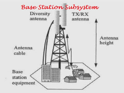
Link Budget of Base Station Subsystem, there are two main parts: Uplink (MS transmit to BTS) and Downlink (BTS transmit MS).
To calculate Minimum Reception Level we need below parameter:
To calculate Minimum Reception Level we need below parameter:
General Character of Position
Character of position that we install Base Station
Transmitting Power Mobile Station
Class 4 (Hand held): Pt(W) =2W Pt (dBm) =10*log(2/10-3) = 33dBm
Transmitting Power Base Station
Class 5: Pt(W) = 20W Pt (dBm) =10*log(20/10-3) = 43dBm
Mobile sensitivity
MS sensitivity = 10*Log(KTB) + Ec/No+ NF
MS sensitivity = [10* Log(1.38 x 10-23 x 300 x 200/10-3)+30] + 8 + 10
MS sensitivity = -120dBm + 8dB + 10dB
MS sensitivity = -102dBm
BTS sensivity
BTS sensitivity = -110dBm (BTS characteristic)
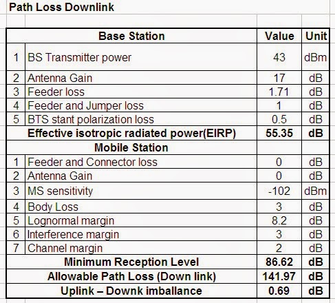
Above result Uplink-Downlink imbalance 0.69dB we can conclude Uplink path loss bigger than Downlink path loss so Mobile Station domain is larger than Base Station domain. In case it can be caused the issue of mobile coverage (no service coverage).
The link budget is an impotant value that enables engineers to design systems based on the required sensitivity of a receiver at a particular distance.
Link Budget of Base Station Subsystem, there are two main parts: Uplink (MS transmit to BTS) and Downlink (BTS transmit MS).
Base Station Subsystem (BSS) in System Architecture of Global System (GSM)
Introduction to System Architecture of Global System for Mobile communications (GSM)
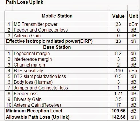
1/ Uplink Path Loss
Mobile Station MS
To calculate Effective isotropic radiated power(EIRP) we need below parameter:- MS Transmitter power
- Loseon Feeder and Connector
- Antenna Gain
EIRP = Transmitter power + Gain Antenna - Feeder and Connector loss
Base Station
To calculate Minimum Reception Level we need below parameter:
- Lognormal margin
- Interference margin
- Channel margin
- BTS sensitivity
- Lose BTS slant polarization
- Body loss
- Lose on Jumper and Connector
- Lose on Feeder
- Diversity Gain
- Receive Antenna Gain
Minimum Reception Level = Receive Antenna Gain + Diversity Gain – Feeder loss - Jumper and Connector loss - Body loss -BTS slant polarization loss - BTS sensitivity - Channel margin -Interference margin- Lognormal margin
Uplink Path Loss Mobile part
Allowable Path loss (Uplink) = EIRP + Minimum Reception Level
2/ Downlink Path Loss
Base Station
To calculate Effective isotropic radiated power(EIRP) we need below parameter:- Base Station Transmitter power
- Antenna Gain
- Feeder Loss
- Feeder and Connector loss
- BTS stant polarization loss
EIRP =Transmitter power + Gain Antenna - Feeder Loss - Connector and Jumper loss - BTS slant polarization loss
Mobile Station
To calculate Minimum Reception Level we need below parameter:
- Feeder and Connector loss
- Antenna Gainin
- MS sensitivity
- Body Loss
- Lognormal margin
- Interference margin
- Channel margin
Minimum Reception Level = Antennat Gain - Feeder Connector loss - MS sensitivity - Body loss - Lognormal margin - Interference margin - Channel margin
Downlink Path Loss Base Station part
Allowable Path Loss (Downlink) = EIRP + Mimimum Reception Level
Herewith example computes Link Budget
General Character of Position
Character of position that we install Base Station
- Antenna Type: APX906515L-T0-0
- Antenna height: 26m
- Region: urban
- Feeder Type: HFC22D(A)LS Cable 2006
- Feeder loss: 3.71dB per 100m
- Feeder length: 46m
Transmitting Power Mobile Station
Class 4 (Hand held): Pt(W) =2W Pt (dBm) =10*log(2/10-3) = 33dBm
Transmitting Power Base Station
Class 5: Pt(W) = 20W Pt (dBm) =10*log(20/10-3) = 43dBm
Mobile sensitivity
MS sensitivity = 10*Log(KTB) + Ec/No+ NF
- K coeffient Boltzmann (1.38 x 10⁻²³J/Ko)
- T temperature (300 Ko)
- B equivalent noise bandwidth (200 KHz)
- Ec/No intrinsic characteristic of the modulator (8 dB)
- NF noise figure of receive (10 dB)
MS sensitivity = [10* Log(1.38 x 10-23 x 300 x 200/10-3)+30] + 8 + 10
MS sensitivity = -120dBm + 8dB + 10dB
MS sensitivity = -102dBm
BTS sensivity
BTS sensitivity = -110dBm (BTS characteristic)


Thanks for sharingFeeder Networks
ReplyDeleteBase station for HVAC smart home control field
ReplyDeleteIt’s interesting that some of the most common office or printer papers are around 80–90 GSM (or 20–24 lb), which balances cost and usability well.
ReplyDeletePost a Comment